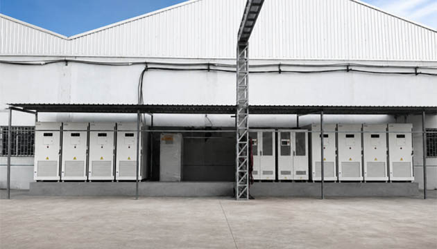
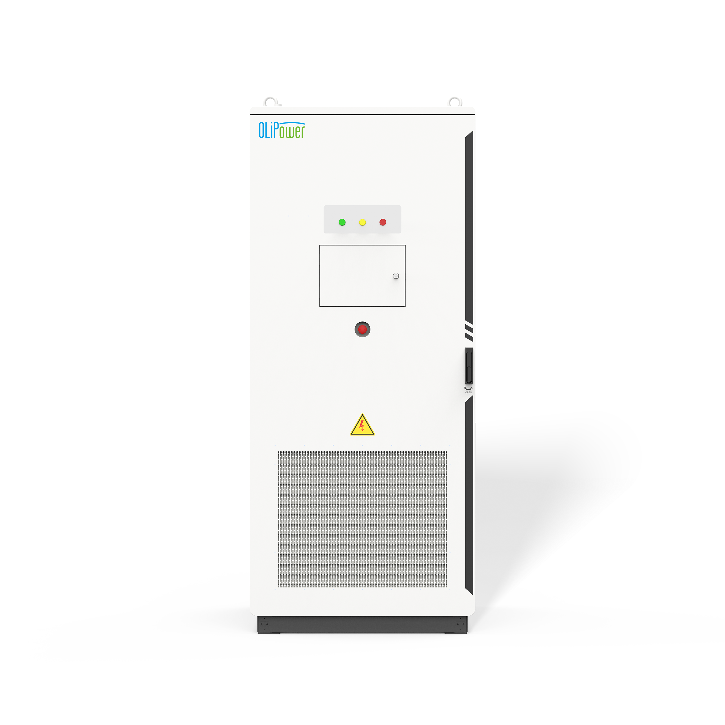
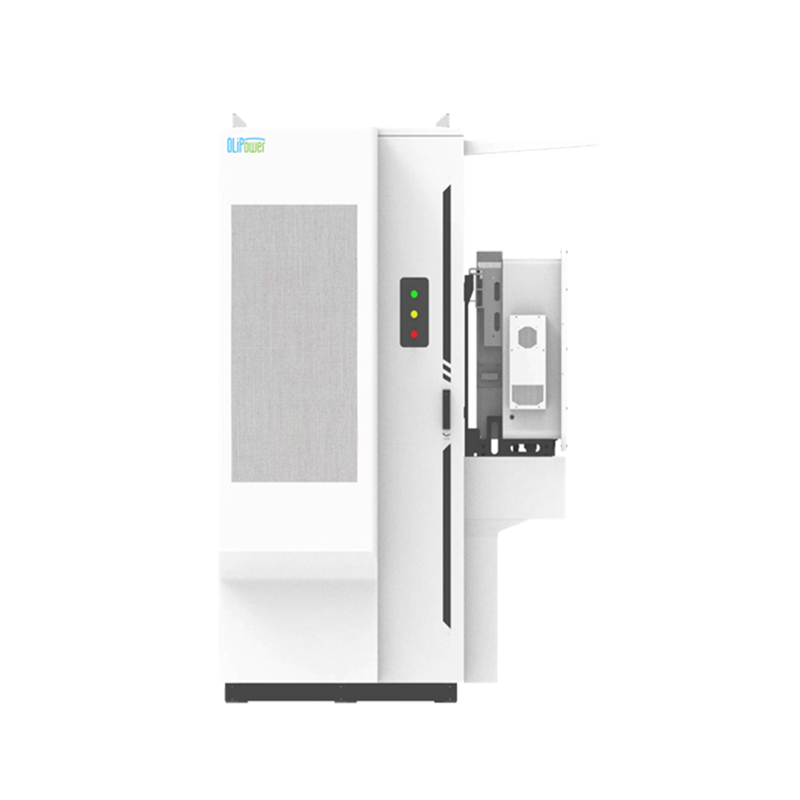
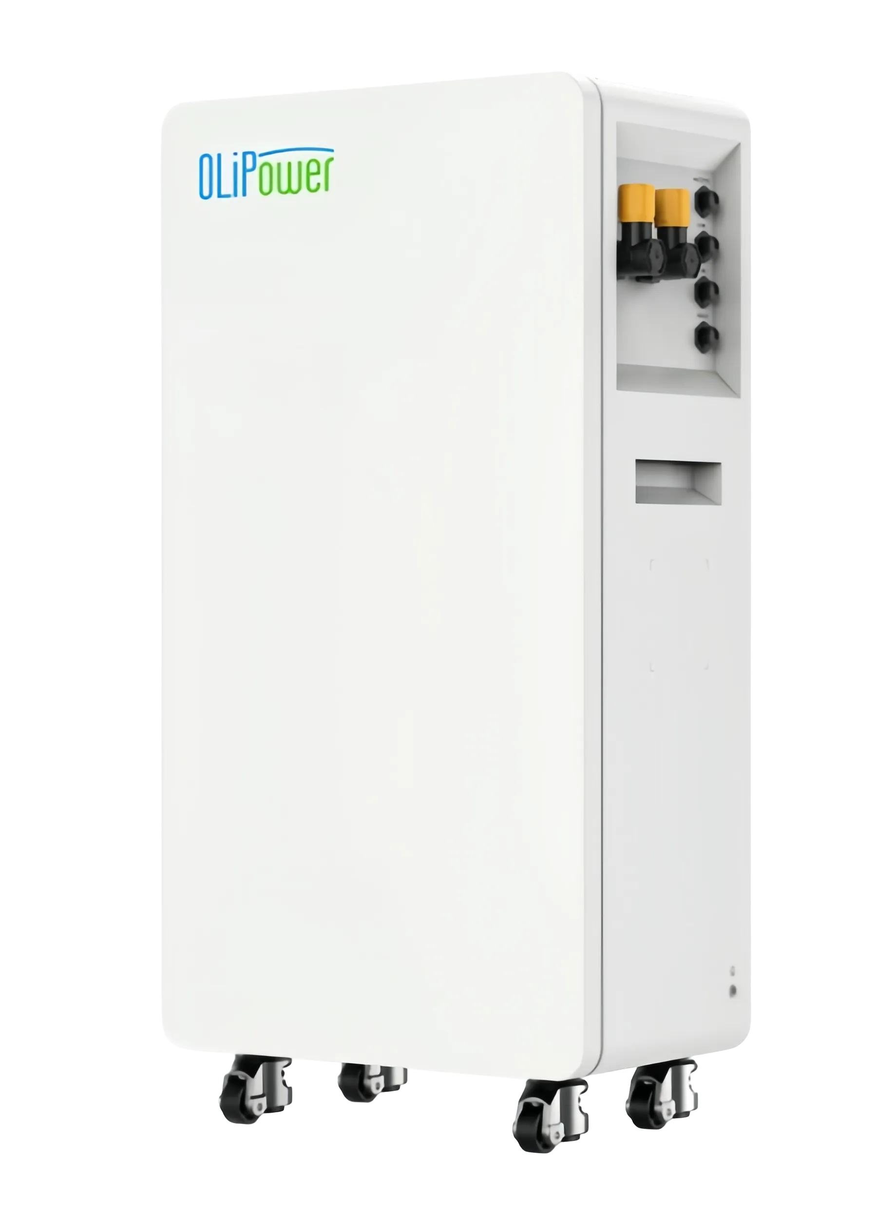
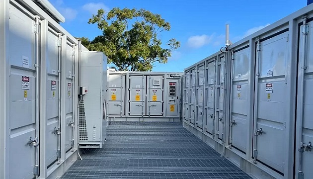
A microgrid is a bounded local power system in which generation, storage, controls and loads must work as one operating system. Selecting a battery is only part of the engineering task: the control strategy must decide when to charge, discharge, preserve backup reserve, curtail generation or start a generator. OLiPower offers integrated hybrid and micro-grid ESS solutions that coordinate photovoltaic power, batteries, diesel generators and the grid. This article focuses on the dispatch rules and transition tests that make those components work together, rather than on a broad list of microgrid applications.
A microgrid operating boundary identifies the sources, loads and protection devices controlled as one system and where it connects to the utility. The boundary affects grid-loss detection, critical-load coverage and restoration logic.
Start with a one-line diagram marking PV inverters, battery PCS, generator breakers, the grid connection, critical-load panels and flexible loads. For each control action, name the owner: microgrid controller, PCS, BMS, generator controller or protection relay.
A dispatch map shows how supply and demand vary over time and when the system must preserve reserve. Include PV output, load variation, generator constraints, battery state of charge and the reserve required for critical operations.
OLiPower’s integrated microgrid energy storage solutions coordinate PV, storage and other sources. Define the EMS scope, who sets priorities, whether forecasts are used and which conditions trigger reserve protection or generator start.
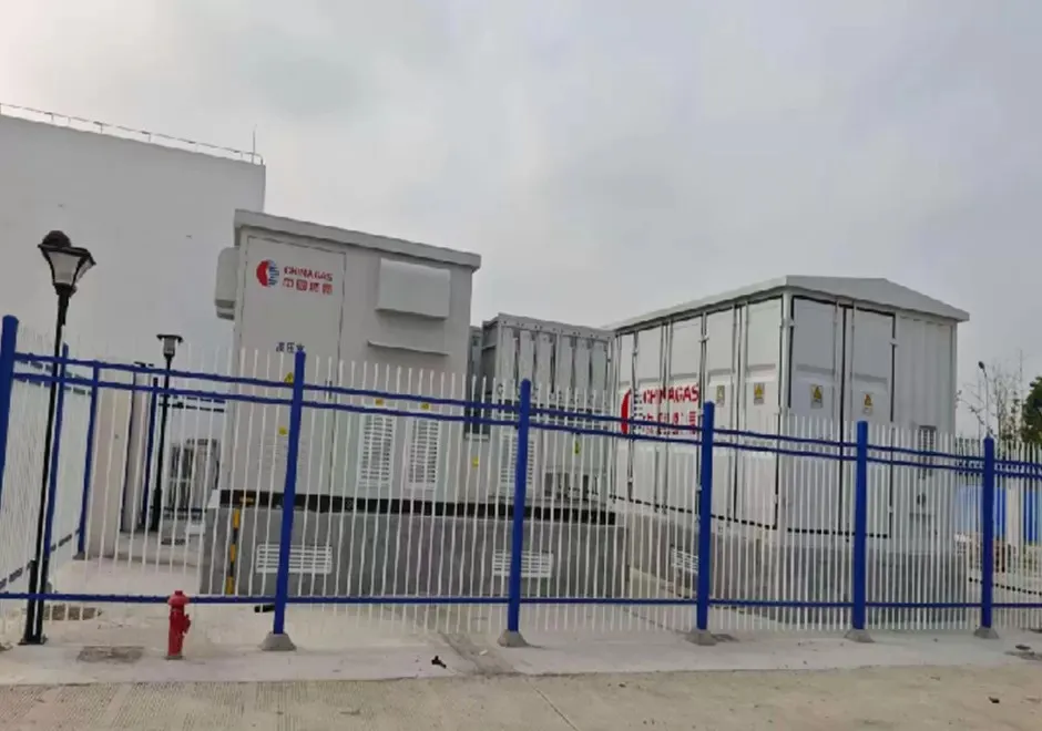
A dispatch priority is an ordered rule describing which source serves which load under a defined condition. It converts goals such as reducing generator use or protecting critical loads into logic that can be tested.
For a solar-led microgrid, a possible sequence is to use available PV for live loads, charge the battery with permitted surplus and discharge storage when solar falls or demand rises. Generator start conditions should be tied to project-approved reserve, load and contingency thresholds.
Specify when priorities change. A battery reserved for outage support may need a minimum state-of-charge target that limits routine energy shifting; generator-supported sites may need distinct logic for loading, charging and source transitions.
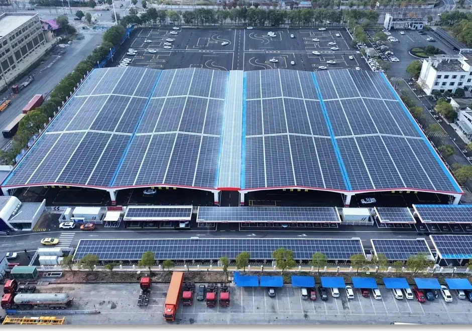
A grid-transition sequence defines how the system detects utility loss, isolates as required, maintains selected loads and returns to grid-connected operation when conditions are acceptable. It must align with protection and switching equipment.
Document triggers, breaker checks, island mode, load-shedding order and restoration permissives. Also define behavior if a signal is missing, a generator fails to start or a battery protection limit is reached. OLiPower lists seamless switching among its microgrid features; confirm the supported boundary and test cases rather than treating the phrase as a universal guarantee.
Battery power determines how quickly electricity can be supplied or absorbed; energy capacity determines how much is available over time. They answer different design questions and should be checked separately.
Use power rating to assess peaks and transients, and usable energy plus dispatch profile to assess duration and reserve. Include temperature, state-of-charge limits, conversion losses and auxiliary consumption; do not infer runtime from a product name alone. When comparing an energy storage product, compare its usable capacity, output rating and control interfaces with the site requirements before choosing a configuration.
OLiPower lists 50kW/111kWh and 125kW/241kWh hybrid cabinets, plus a 500kW/1446kWh hybrid container. These are starting points for evaluation, not substitutes for matching usable energy, transient power, expansion and operating mode to the site.
A microgrid architecture arranges generation, storage, conversion, controls and protection for one site. Good design balances fit, commissioning access, maintenance and plausible future expansion.
A compact cabinet may suit a smaller facility, while containerized equipment can suit larger industrial or remote deployments. When evaluating a configuration in the micro ess category, compare source compatibility, controls, installation method, maintenance access and expansion path—not just footprint.
Apply the same evaluation worksheet across candidate systems, covering rated and usable energy, output power, operating modes, interfaces, protection, service conditions and documentation. This keeps procurement tied to application fit.
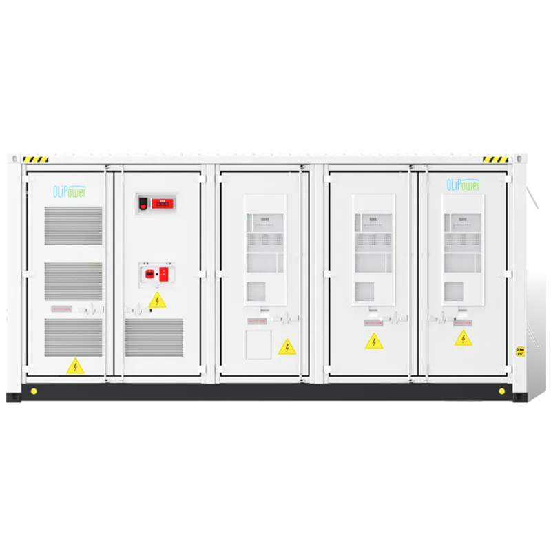
Scenario-based commissioning verifies full control sequences under normal and abnormal conditions. It should prove both that devices communicate and that the controller makes the intended decision as site conditions change.
Agree a matrix covering PV surplus, rapid load increase, low reserve, utility interruption, generator start/stop, communications fault and restoration. Record the initiating condition, expected response, measured evidence and sign-off for each test.
Scenario | Control objective | Evidence to record |
PV exceeds live load | Charge only within permitted battery and inverter limits; manage any remaining surplus | Power trends, SOC change, alarm status and export/curtailment behavior. |
PV drops while load rises | Discharge storage or start other generation according to the approved priority order | Setpoint tracking, source-sharing behavior and critical-load voltage/frequency records. |
Utility supply is lost | Execute the agreed isolation and islanding sequence | Breaker/status logs, transition trace and confirmation of served critical loads. |
Battery reserve reaches threshold | Preserve reserve or bring another source online as designed | Threshold event, controller decision and resulting generator or load action. |
Communications are interrupted | Move to the documented fallback or safe state | Alarm timestamp, timeout action, local protection behavior and recovery record. |
A sequence-of-operation document that defines sources, loads, modes, trigger conditions, protection interfaces, state transitions and acceptance criteria.
Not necessarily. Charging depends on reserve targets, battery limits, export rules, upcoming load and the project’s operating priorities.
Identify them separately, estimate their power and energy needs, and specify the reserve and transition behavior required to keep them supplied.
A system-level controller can coordinate these resources when the architecture and interfaces support it. Confirm the exact control scope and responsibility split for the offered project.
No. The project still needs defined operating boundaries, supported equipment, protection coordination and documented scenario-based acceptance tests.
Include final drawings, sequence of operation, point and alarm lists, test reports, operator training material, manuals and a clear escalation process.
Microgrid reliability is shaped by explicit priorities and tested transitions, not by battery capacity alone. OLiPower’s hybrid and micro-grid ESS portfolio provides cabinet and container options designed to coordinate renewable generation, batteries, generators and grid connections. A project-specific dispatch workshop is the best next step for translating those capabilities into an agreed control sequence and acceptance plan.
Ready to size your next project?
Contact our engineering team today:
Online Inquiry Form: https://www.olipowerenergy.com/contact.html
Email: sales@olipower.cn
1. U.S. Department of Energy: Microgrid Systems
2. U.S. Department of Energy: Solar Integration — Distributed Energy Resources and Microgrids Basics
3. U.S. Department of Energy: Energy Storage RD&D