Round-trip efficiency is one of the first numbers buyers look at when comparing battery energy storage systems. It appears simple: charge the BESS with a certain amount of electricity, discharge it later, and measure how much energy comes back.
This guide explains how BESS round-trip efficiency (RTE) is calculated, why DC and AC efficiency values differ, where losses occur, and what project developers should check before using a supplier's efficiency figure in an energy or financial model.
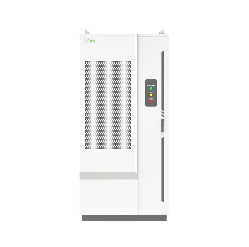
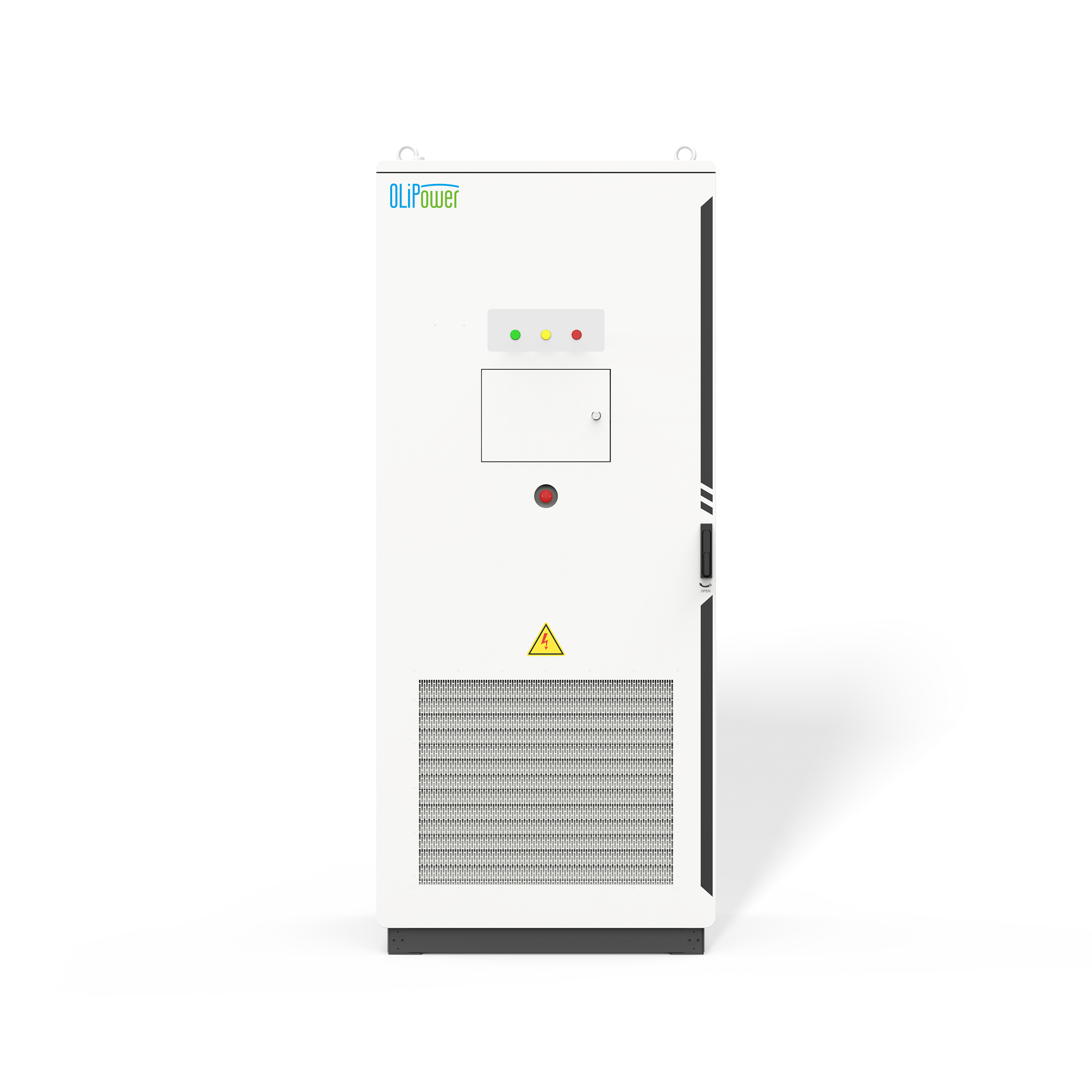
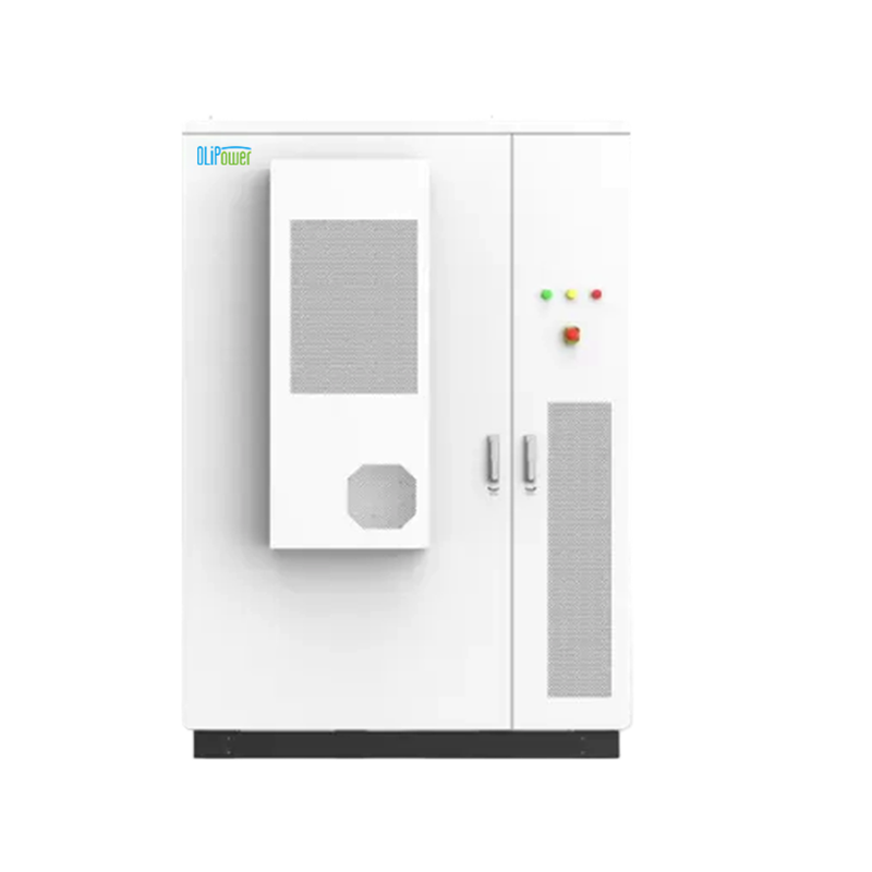
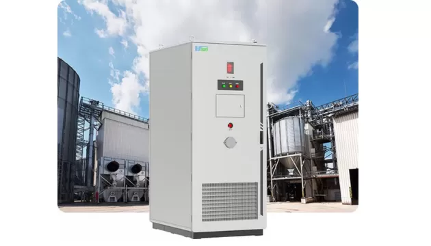
As a leading source-factory manufacturer specializing in OLiPower liquid-cooled C&I cabinets and 5MWh containerized utility-scale systems, we frequently help clients dissect how real-world engineering impacts these numbers. This guide explores how BESS round-trip efficiency is calculated, where energy losses occur, and how OLiPower’s advanced system design optimizes real-world site efficiency.
For projects involving peak shaving, solar integration or load shifting, system efficiency should also be considered together with the overall C&I energy storage solution rather than evaluated as an isolated battery specification.
BESS round-trip efficiency is the percentage of electrical energy recovered from a battery energy storage system after a complete charge-and-discharge cycle compared with the electrical energy used to charge it.
If 1,000 kWh enters the defined system boundary and 900 kWh is returned during discharge, the round-trip efficiency is 90%.
The remaining 100 kWh has not disappeared. It has been consumed or dissipated through battery resistance, power conversion, cables and transformers, thermal management, control equipment and other auxiliary loads.
This makes RTE different from several other numbers that may appear on a datasheet:
| Metric | What It Describes | What It Does Not Necessarily Include |
| Cell efficiency | Electrochemical performance of an individual cell | BMS, cables, PCS, cooling, transformer |
| Battery/cluster efficiency | Performance at battery or cluster level | AC conversion and many system auxiliaries |
| PCS efficiency | AC/DC or DC/AC conversion performance | Battery losses and other BESS loads |
| DC round-trip efficiency | Charge and discharge performance measured on the DC side | Full AC-side system losses |
| AC round-trip efficiency | Energy returned compared with energy supplied at defined AC measurement points | Transformer or external auxiliaries unless explicitly included |
This distinction matters because battery energy storage efficiency is only meaningful when the measurement boundary is clear.
As a useful industry benchmark, NREL's utility-scale battery storage modeling has used an 85% round-trip efficiency assumption. This is a modeling assumption rather than a specification every lithium-ion BESS should meet, but it illustrates why project-level RTE should not automatically be equated with a high battery-cell or inverter efficiency figure.
Real operating results can also differ from laboratory or nameplate figures. Historical U.S. Energy Information Administration data showed an average monthly RTE of approximately 82% for the U.S. utility-scale battery fleet in 2019. Operating profile, auxiliary demand, climate and equipment generation all influence actual results.
The basic calculation is:
Round-Trip Efficiency (%) = Energy Discharged ÷ Energy Charged × 100
For example, suppose a BESS receives:
Energy charged: 5.0 MWh
Energy discharged: 4.5 MWh
The calculation is:
4.5 MWh ÷ 5.0 MWh × 100 = 90% RTE
At first glance, this seems straightforward. The difficult part is deciding where the 5.0 MWh input and 4.5 MWh output are measured.
If both measurements are made at the battery DC terminals, the result is a battery-side value.
If electricity is measured at the AC terminals of the complete BESS before charging and again after discharge, the result can represent AC-to-AC system RTE.
If cooling and controls are connected to a separate auxiliary power source, their energy consumption must also be accounted for if the objective is to understand the real efficiency of the installation.
Consider a project that sends 5 MWh into storage every day.
At 90% RTE, approximately 4.50 MWh is returned per cycle.
At 88% RTE, approximately 4.40 MWh is returned.
The difference is only 0.10 MWh per cycle, but across 365 daily cycles that becomes approximately 36.5 MWh of additional energy delivered per year.
The financial value of that difference depends on electricity prices, operating schedules and the revenue model. This is why RTE becomes especially relevant for frequently cycled applications such as peak shaving and energy arbitrage.
A common reason for apparently conflicting BESS efficiency specifications is that one value is measured on the DC side while another is measured on the AC side.
DC efficiency focuses primarily on the battery system. Depending on the supplier's definition, the measurement may be taken at cell, module, pack or cluster level.
It therefore avoids some of the losses introduced by the PCS, transformer and AC-side equipment.
DC figures are useful when comparing battery technologies or battery subsystems, but they should not be used directly to estimate the amount of AC electricity a facility or grid will receive.
AC round-trip efficiency measures a broader energy path.
Electricity must be converted from AC to DC during charging and then from DC back to AC during discharge. Depending on the specified measurement boundary, transformer, cabling and auxiliary consumption may also be included.
For most C&I and grid-connected projects, this is generally the more useful figure for energy modeling because the customer buys, generates or exports electricity on the AC side.
| Comparison | DC Efficiency | AC Round-Trip Efficiency |
| Typical measurement point | Battery DC terminals | Defined AC input/output point |
| Battery losses | Included | Included |
| PCS conversion losses | Usually excluded | Included |
| Thermal management | Depends on test boundary | Should be clarified |
| Auxiliary loads | Often excluded | May be included or separately accounted for |
| Transformer losses | Excluded | Depends on measurement point |
| Best used for | Battery subsystem comparison | Project energy and economic analysis |
The difference is also visible in PV-plus-storage modeling. NREL has used different efficiency assumptions for grid-charged batteries and batteries charged from coupled PV because the electrical conversion path is different.
The key lesson is not that one architecture always has a fixed efficiency advantage. It is that the electrical path and measurement boundary affect the RTE number being reported.
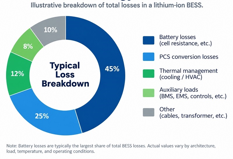
Energy loss does not happen at a single component. It accumulates across the complete storage system.
| Loss Source | Why Energy Is Lost | What to Check |
| Battery cells and connections | Internal resistance and electrochemical losses generate heat | Chemistry, C-rate, temperature and SOC range |
| PCS | Energy is lost during AC/DC and DC/AC conversion | Efficiency curve, not only peak efficiency |
| Transformer and cabling | Electrical resistance and magnetic losses | Whether these are inside the quoted RTE boundary |
| Cooling or HVAC | Fans, pumps, compressors and heaters consume electricity | Climate conditions and thermal strategy |
| BMS, EMS and controls | Electronics remain powered during operation and standby | Auxiliary and standby consumption |
| Safety systems | Sensors, communication and protection devices require power | Whether auxiliary energy is included |
| Standby periods | A BESS can consume energy even when it is not charging or discharging | Idle duration between cycles |
One important point is that these losses do not simply disappear when the battery is idle. A BESS used for one full cycle every day may have a very different effective efficiency from the same system performing short, intermittent dispatch events while remaining energized for long periods. For that reason, a project developer should distinguish between cycle RTE measured under a defined test and the broader operational energy efficiency seen over weeks or months.
Achieving superior site-level efficiency requires more than high-spec cells; it demands co-optimized hardware architecture.
In extreme ambient climates, traditional HVAC systems can consume excessive auxiliary power, dragging down net site RTE. OLiPower’s liquid-cooled C&I and utility-scale containerized systems utilize intelligent thermal management and precision flow control. By maintaining uniform cell temperatures within an optimal narrow window, OLiPower systems minimize internal resistance while preventing excessive parasitic cooling loads—ensuring nameplate efficiency translates into real-world performance.
The Power Conversion System (PCS) operates during both charging and discharging cycles. OLiPower integrates high-efficiency bi-directional PCS units engineered to maintain high conversion efficiency across wide load ranges, rather than only at peak laboratory points. This mitigates compounding losses during partial-load operations.
No. Higher round-trip efficiency is valuable, but RTE alone is not enough to select a BESS.
The objective of an energy storage project is not to produce the highest possible efficiency percentage in one controlled test. It is to deliver the required energy, power, safety, availability and financial performance over the planned operating life.
A system with slightly higher RTE may still be the weaker project choice if it has an unsuitable power rating, limited usable capacity, rapid degradation or inadequate thermal management.
Conversely, some auxiliary energy consumption can be justified when it supports better temperature control, system safety or long-term battery health.
For C&I and utility projects, RTE should therefore be considered alongside:
usable energy capacity and power;
expected charge/discharge rate;
cycle and throughput requirements;
battery degradation;
temperature range and thermal management;
system availability;
safety and certification requirements;
PCS and EMS compatibility;
warranty conditions; and
lifetime project economics.
Efficiency also needs to match the real duty cycle. A system optimized for an attractive RTE at low power may not deliver the same result when a project regularly charges or discharges at a much higher rate.
There is no single percentage that applies to every BESS because the result depends on the measurement boundary and operating conditions. Project-level AC RTE should be compared only when suppliers use equivalent system boundaries and test conditions.
Divide the energy delivered during discharge by the energy required during charging and multiply by 100. A system that returns 900 kWh after receiving 1,000 kWh has a 90% RTE.
No. Battery efficiency may describe cells, packs or battery clusters on the DC side. Full BESS efficiency can also include PCS conversion, thermal management, auxiliary consumption and other system losses.
AC RTE includes additional conversion stages. Electricity normally passes through the PCS during both charging and discharging, and depending on the measurement boundary, transformer and auxiliary losses may also be included.
Yes. Temperature influences battery resistance and thermal-management demand. Cold conditions can increase battery resistance, while hot conditions can require more cooling and accelerate degradation if they are not properly controlled.
It can change as the system ages because cell resistance, capacity and operating behavior change over time. For long-term financial modeling, buyers should consider degradation and guaranteed performance rather than relying only on a beginning-of-life efficiency value.
A headline efficiency percentage has little value unless you know the measurement boundary, auxiliary inclusions, and operating profile behind it.
As a trusted source-factory manufacturer offering full-stack self-developed BMS, PCS, and thermal architectures, OLiPower helps developers eliminate guesswork.
Ready to size your next project?Contact OLiPower today with your required kW/MW, kWh/MWh, daily duty cycle, and site environmental conditions. Let our engineering team evaluate your system architecture and model true AC-side efficiency for your application.